PLC is widely used in the equipment control of mechanical manufacturing, but in the numerical control transformation of ordinary lathe, the use of PLC as the core component of the numerical control system is still a new topic. With the continuous improvement of PLC technology and functions, this will be a development trend. This article discusses this. 2 Control design of PLC numerical control system for lathe 2.1 Operating requirements for lathes Lathes generally process rotary surfaces, threads, and the like. It is required that the action is generally fast forward, work forward, and rewind in X and Z directions. Automatic, manual, outer circle and thread conversion can be performed during the machining process; and single step operation is possible. 2.2 PLC numerical control system needs to be solved The operation process of the lathe is complicated, and the PLC is generally only suitable for the sequential control of the action. To use the PLC to control the lathe action, three problems must be solved: 1) How to generate the signal for driving the servo mechanism and the coordination of the X and Z directions; 2) How to change the feed system speed; 3) How the thread realizes the change of the internal contact drive and the thread lead. These problems can be solved by combining the PLC and its control modules with the corresponding actuators. 2.3 Control principle of CNC system The numerical control transformation of the ordinary lathe is to change the tool holder, X, Z feed to CNC control. According to the characteristics of the transformation, the servo component adopts a stepping motor, and the open loop control system can meet the requirements. The Z-direction pulse equivalent is taken as 0.01 mm, and the X-direction pulse equivalent is taken as 0.005 mm. Select the PLC of the transistor output type. The stepping motor pulse signal is driven by programming, and the program generates different frequency pulses to realize the shifting. The X and Z directions can be automatically controlled by inputting manual operations or programs. The pulse signal of the thread is generated by the spindle pulse generator, and is connected to the PLC input through the AND circuit, and the pulse of the required lead is obtained by the PLC program frequency conversion. Tool post indexing, turning tool advance and retract can be controlled by manual or automatic program. Figure 1 is a schematic diagram of the numerical control system. [1] Next page Wire Basket,Medical Equippmet Basket,Stainless Wire Mesh Basket Anping Tianshun Metal Net Co., Ltd. , http://www.chawiremesh.com
1 Introduction 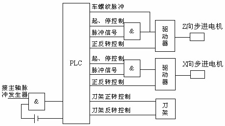
Figure 1 Schematic diagram of the CNC system