Thin-walled parts have been increasingly used in various industrial sectors because of their light weight, material saving, energy saving, and compact structure. However, thin-walled parts are a difficult problem in machining and cutting. Due to the poor rigidity of thin-walled parts, the processing is easily deformed, and the shape and position errors of the parts are increased, so it is difficult to ensure the processing quality of the parts. The thin-walled thin-walled parts shown in Figure 1 are the rotor-type oil pump body developed by our company for the SAIC KV6 engine. The material is YL112 aluminum alloy die-casting, which is also one of the more difficult parts of the company. . Due to the large output and high quality requirements, we have carefully studied the process plan of the part processing, and tested the workpiece clamping, tool angle and cutting amount selection, and program preparation. The deformation and vibration pattern appearing during the processing of the part ensure the processing precision and quality, and provide effective experience and examples for processing such thin-walled parts. 1. Part structure and process analysis The disc-shaped part is composed of irregular triangles, the thickness of the surrounding area is only 5 mm, and the thinnest part in the middle is only 2. 5 mm, and there are irregular grooves in many places, and the maximum rotating diameter is 335 mm. Such a structure Complex parts, uneven thickness, and large special parts, the processing difficulty is mainly the following two points: (1) Due to the insufficient rigidity of the large surface of the part surface, the pressing point and the supporting point are relatively far apart, and plastic deformation is likely to occur when the cutting force is applied. (2) During cutting, due to the self-excited vibration of the machine tool, intermittent cutting causes irregular cutting vibration, plus other mechanical vibrations of the clamp and the outside, and improper selection of the tool angle, etc., causing vibration of the surface to be cut. Grain, seriously affecting the processing quality of the surface of the part. 2. Processing technology The processing route of the part: die-casting blank→surface blasting→drilling screw hole→coarse, fine car joint surface and rotor hole→rough, fine car back and round table plane hole→milling sealing groove→test acceptance, etc. The above main processes are in numerical control Completed on lathes and machining centers. When implementing the above processing steps, the reasonable arrangement of the steps should be controlled to effectively control the deformation of the workpiece during cutting to ensure the depth dimension of the rotor holes. It should be carried out on the principle of first coarse and fine, first and then far, inner and outer cross, and base surface first, that is, first roughing the joint surface, then roughing the rotor hole, then finishing the rotor hole, and finally finishing the joint surface. By cross-processing, the generation of thermal stress deformation can be reduced. Next page 2D Wired Handheld Industrial Barcode Scanner Industrial Qr Code Reader,Industrial Bar Code Scanner,Pos Laser Barcode Scanner,Industrial 2D Barcode Scanner Guangzhou Aigather Intelligent Technology Co., Ltd. , https://www.aigathergz.com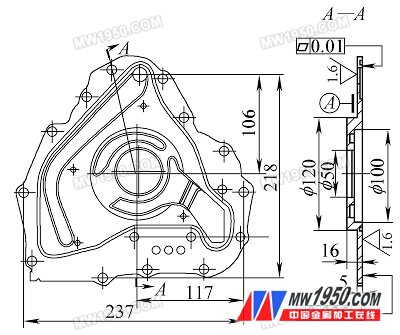
figure 1