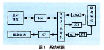
1 Introduction At present, in the oil pump nozzle industry, the traditional nozzle processing relies mostly on the manual operation determined by individual skills, the product quality is unstable, the production efficiency is low, the labor intensity is high, and the scrap rate is high. The system is designed for an EDM machine. The discharge of the negative electrode is used to discharge the workpiece to achieve the processing purpose. Through the test, the wear ratio of the brass to the workpiece is obtained, and the machining depth required by the program is controlled. The processed nozzle seat surface completely meets the requirements, the processing speed is improved, the machining precision is ensured, and the traditional wind grinding process is completely replaced. 2 design ideas According to the nozzle processing technology and the parameters of the workpiece, the stepper motor drives the electrode to move, and it is necessary to accurately and automatically sample in real time, and change the working frequency of the stepping motor to control the feed of the stepping motor, in order to meet the seat surface of the nozzle. It is required that in the process of processing, according to the loss ratio obtained by the test, the table-reading method is used to correct the electrode in real time, which is controlled by the grinding wheel motor. According to the processing depth of different rough workpieces, the corresponding frequency and the number of steps to control the operation are taken. Its process sequence control logic includes: (1) Rapid advancement: In order to improve work efficiency, after the workpiece is installed, the stepping motor must quickly advance to the surface of the workpiece to be machined. We use a three-phase stepping motor (45BF3) as the feed drive component of the electrode. The stepping motor that is controlled has three basic working modes: forward rotation (infeed), reverse (retraction) and stop rotation. The forward and reverse have different operating frequencies (ie, infeed or retract speed). The feed and retract speed are adjusted according to the software. When the three-phase winding of the stepping motor is energized in the order of A→AB→B→BC→C→CA→A, the forward rotation can be realized. Otherwise, if A→AC→C→BC→B→AB→A is pressed When the sequence is energized, the reversal can be realized. If the output state remains unchanged, the motor will stop running. The three-phase winding of the motor is controlled by P1.0, P1.1, and P1.2 of the P1 port of the 8031. Control how it works. During the machining process, the machining voltage and the discharge capacitor should be controlled at the same time. When repairing the machining electrode, the voltage of the workpiece and the motor should be switched. These are software to control the opening and closing of each relay according to a certain timing. 3 system hardware design The hardware of this system consists of four parts, namely the basic system consisting of 8031 ​​MCU, 2764EPROM and 74LS373, drive circuit, sampling circuit and display and keyboard scanning circuit. Here we mainly introduce the basic system and drive circuit. 3.1 basic system The system has set up a 5-digit display and 7 buttons. The display shows the processing mode status, setting value and machining remaining amount. The seven buttons are: start, reset, pause, ten position digits, position digits, set function keys. , processing mode selection, when the set number button works, you can set the number of ten and the number, the processing mode can choose coarse grinding, coarse grinding processing. In the software, the processing amount of 1 to 99 filaments is converted into corresponding data according to a certain conversion relationship and stored in a table, and the data in the corresponding table can be taken according to different processing amounts during processing. The LED display and keyboard are connected by a serial input, parallel output shift register 74LSl64. The system schematic is shown in Figure 1. Water Glass Pipes,Tobacco Pipe,Hookah Chisha Pipes Hookah Co., Ltd , http://www.zjhookah.com
(2) Quick retraction: After the preset machining amount is processed, the stepping motor must be returned to the initial position.
(3) Rough grinding: For the processing of large blanks, in order to improve the working efficiency, it is possible to select rough machining separately. When roughing, the stepping motor feeds at the rough grinding speed, and at the same time, by changing the discharge voltage, switching the discharge capacitance and controlling Discharge sparks, discharge quickly, and increase processing speed.
(4) Fine grinding: When the processing size is small, in order to ensure the angle and smoothness of the seat surface, the fine grinding method is adopted. When the grinding is fine, the discharge spark is small and the machining voltage is low. This is also to switch the machining voltage and discharge through the software control relay. Capacitance is achieved.
(5) Coarse fine grinding: This system can be finished by rough grinding. Rough grinding is used at the beginning of processing. When the machining is within a certain range (such as 3 filaments), the system automatically converts to machining, which not only improves the processing speed, but also ensures the accuracy and smoothness. The system can control the amount of spark discharge in two processing modes.