Product categories of Ridge Cap Roll Forming Machine,we are specialized
manufacturers from China,Ridge Cap Roll Forming Machine,sheet rollforming machine,
suppliers/factory,wholesele high-quality product of Ridge Cap Roll Forming Machine,
R & D and manufacturing , we have perfect after-sales service and technical support . Look forward
to your cooperation !
Ridge Cap Roll Forming Machine Ridge Cap Roll Forming Machine,Ridge Panel Roll Forming Machinery,Ridge Tile Roll Forming Machinery,Ridge Sheet Roll Forming Machinery BOTOU HUATONG CORRUGATED MACHINERY MANUFACTURING CO.,LTD , https://www.htrollforming.com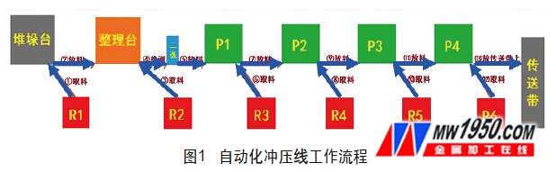


Stamping automation control principle and fault analysis
In order to improve production efficiency and improve the degree of stamping automation, in 2013, our company introduced stamping automation technology from South Korea, and replaced the manual operation by robot operation. The PLC control replaced the manual control, and two stamping automation production lines were installed. Quickly mastering, digesting, and absorbing the automation control system technology and principles are very helpful for us to optimize the commissioning, transformation and innovation of the automated production line and routine maintenance, and rapid maintenance under sudden conditions.
1. Automation line configuration
The configuration of the automation line mainly includes presses, robots and automation systems. The presses are Worth Seiki JH21-200, JH21-250, JH21-315; South Korea Shinpei 400t, 600t, 1000t. Robot Japan Yaskawa robot MH50, ES165D. Automation system (Korea): Operation console - Mitsubishi Q, CC-link 32DT, stacking table × 2, finishing table, conveyor belt × 2.
2. Principle of automatic operation control
(1) Overview of automated press line As shown in Fig. 1, red R represents a robot and green P represents a press. The working sequence of the automated press line is as follows: (1-2) R1 sucks the material from the stacking table and places it on the finishing table. (3-5) R2 sucks the material from the finishing table and places it in two detection positions for inspection, and then puts it into P1 for punching. (6-7) R3 sucks up the punched piece in P1 and sends it to P2 for stamping. (8-9) R4 sucks up the punched piece in P2 and sends the piece to P3 for stamping. (10-11) R5 sucks up the punched piece in P3 and puts it into P4 for stamping. (12-13) R6 sucks up the punched piece in P4 and places it on the conveyor. These 13 steps are carried out and reciprocated.
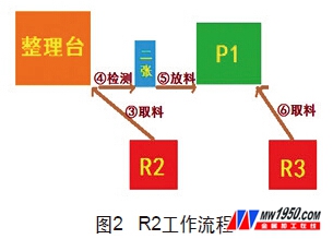
(2) The process of taking and discharging materials is to learn more about how the punching line in the automation realizes the cooperation between the robot and the punching machine. We take the action analysis of the robot R2's reclaiming, detecting, loading and robot R3 reclaiming process as an example. Figure 2 shows.
In the first step, the robot 2 takes the material from the finishing table. As shown in Figure 3, when there is a piece of material on the finishing table, the proximity sensor on the finishing table will be inductive and the indicator light will be bright. And when the robot R1 does not feed the sheet to the finishing table, the finishing station sends a signal to the robot R2 requesting the robot R2 to take the material.
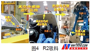
When the robot R2 receives this signal, it starts moving over the sheet of the finishing table and prepares to suck. As shown in Figure 4, the vacuum sensor monitors when the robot R2 draws. When the web is sucked, the display on the vacuum sensor will turn red and the signal will be fed back to the robot R2. The transfer to the robot R2 is sucked and the next step can be performed. Then, the robot R2 sucks the web away from the finishing table and advances to the two detected positions. The function of the vacuum sensor is to ensure that the robot R2 sucks the web.
The second step, two tests. As shown in Fig. 5, at this time, the robot R2 has taken the web to the two detected positions for detection. The purpose of the two tests is to detect the thickness of the suction piece of the robot, and to ensure that only one piece of material enters the punch P1 for punching. If the detection device detects normal, there is only one piece of material, the sensor displays green, indicating that the test is qualified, and the robot R2 executes the loading program. Otherwise the sensor is displayed in red and the robot P2 executes the throwing program.
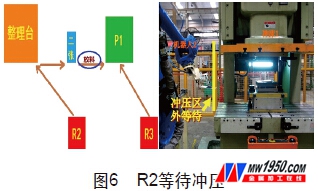
The third step is to feed, punch, and leave. As shown in Fig. 6, if the two detections confirm that the robot R2 only sucks one piece of material, the robot R2 will take the piece of material to the outside of the punching area of ​​the punching machine 1 to wait, here to ensure that the robot is only in a safe situation. Enter the stamping area.
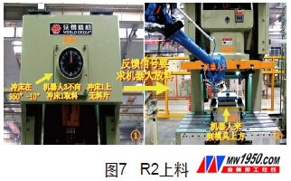
As shown in Fig. 7, when the punching machine is in the range of 350° to 10°, the robot R3 does not feed the punching machine P1, and the punching machine P1 has no material, the feedback signal is given to the robot 2 to request the robot to the punching machine P1 mode. Area discharge. The robot 2 then takes the web to the top of the press P1 mold. This is a protective condition to ensure that the robot R2 does not discharge when the punching machine P1 is punched, and the robot R2 does not discharge the material when the robot R3 takes out the material, and does not discharge the material when the punching machine P1 is in stock, which is the safety protection mentioned above.
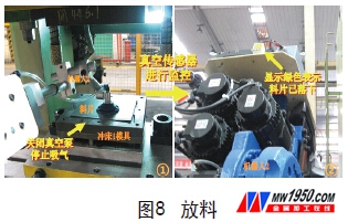
As shown in Fig. 8, when the robot R2 comes to the top of the mold with the web, a signal is output to the vacuum pump, and the vacuum pump is required to be turned off to stop the suction. At the same time, the vacuum sensor is monitored. If the vacuum sensor has no signal and is displayed in green, it indicates that the blank has been lowered. The function of the vacuum sensor here is to ensure that the web falls in the stamping area.
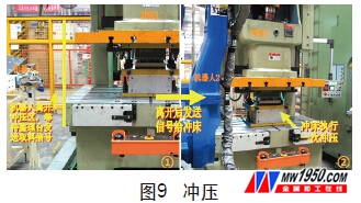
As shown in Figure 9, when the vacuum sensor does not sense the inhalation, the robot R2 will directly receive the signal that the piece falls on the mold, so the robot R2 leaves the punching work area and waits for the finishing station to send the reclaiming of the robot next time. signal. After the robot R2 leaves, a signal is sent to the press P1, indicating that it has reached the safe area and can be stamped. When the punch P1 receives the signal, a punch is performed. This time also serves as a protection to ensure that no robots discharge material during stamping to ensure equipment safety.
In the fourth step, the robot R3 takes the material. As shown in Fig. 10, at the same time, the robot R3 waits outside the punching zone of the press P1. When the press P1 is stamped once, it will send a signal to the waiting robot R3. When the press machine P1 is in the range of 350° to 10° and the press machine P1 is in stock, and the robot R2 is not discharged to the press machine P1, the robot R3 starts to operate to perform the take-up process. The principle of reclaiming is the same as that of the robot R2. In this way, the reclaiming, detecting, feeding and stamping of the robot R2 completes a cycle, and the other cycle is simply described. The communication mode of the signal is applicable to the entire automation system.
3. Robot R2 action PLC control principle detailed
In the process of picking and discharging, we made a simple PLC action analysis for the workflow of the robot R2. However, to understand the connection between the robot and the PLC, the signal between the press, or to modify and optimize the automation system in the future, we need to understand the internal procedures of the robot and PLC. Therefore, we took out the loading, stamping, and leaving of the last section of the robot R2 during the movement, and conducted a more in-depth analysis at the program level. The loading process of the robot R2 is started after the two pieces of material have passed the test.
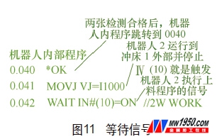
As shown in Figure 11, after the two tests pass, the PLC will input a signal to the robot, so the robot R2 executes the internal loading program. As shown in the figure, the internal program of the robot jumps to 0040 *OK. Then the robot 2 runs outside the punching area of ​​the punching machine 1 and stops waiting, waiting for the signal IN10, which is a signal that triggers the robot R2 to execute the loading program (MOVJ is a program for the robot to operate the robot to the target position).
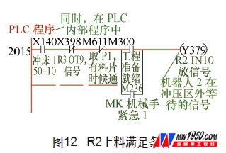
As shown in Fig. 12, at the same time, in the PLC internal program, when the press P1 is at 350° to 10°, the robot R3 is not fed to the press P1, and the punching machine P1 is free of material, the punching machine is satisfied. The signal Y379 (IN10) will be output to the PLC. This is the signal IN10 that the robot R2 waits outside the punching zone, and this signal is input to the robot R2 through the PLC. The meaning of this procedure is that when the above conditions are met, the press P1 will tell the robot that R2 can now enter the stamping area.
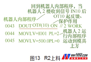
As shown in Figure 13, returning to the internal program of the robot, when the robot R2 receives the signal IN10, it will execute the internal program and output the signal OT10. This signal serves as feedback and protection, meaning that after sending this signal, the machine R2 During this process, the punch P1 is not allowed to punch and the robot 3 is not allowed to take the material into the press P1, thus ensuring that there is no dangerous accident between the robot and the press due to signal conflict. After signal OT10 is issued, robot R2 performs an internal program to move the web above the die 1 die.
As shown in Figure 14, when the robot R2 sucks the material to the top of the punching die, it outputs the signal OT16, and inputs the OT16 to the PLC, and then passes the PLC output signal Y36B. The Y36B will turn off the vacuum pump on the robot R2 to make it Stop inhaling and stop waiting. Thus, the web will fall on the mold of the punch 1.
As shown in Figure 15, the vacuum sensor on the robot R2 is always monitored. When the material falls, the vacuum sensor will monitor no material, so that the PLC normally closes the soft original X349 channel and directly inputs the signal X349 to the PLC. Then the PLC outputs the signal IN16, and inputs IN16 to the robot, telling the robot that the piece of material is indeed on the mold, and can proceed to the next step. This is the signal that the robot stops waiting after the material is placed.
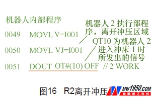
As shown in Fig. 16, after receiving the signal IN16, the robot R2 executes the internal program, leaves the punching area, and outputs a signal OT10 issued when the signal is turned off before entering the punch P1, telling the PLC that it has left, and the punching machine from now on. Both the punching of P1 and the retrieving of robot R3 are allowed to run (OT10 is the signal emitted when robot R2 enters punch P1).
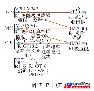
As shown in Fig. 17, at this time, the robot R2 returns to the origin, and sends a signal OT11 to the PLC, and then this signal passes through a conversion output Y150 inside the PLC, and is input to the punch 1 through the PLC. When the press P1 receives the signal Y150, a punching operation is performed. At this point, the robot R2 completes the process of loading, leaving, and stamping.
4. Maintenance and troubleshooting of automated press line
The automatic press line consists of a PLC control cabinet, 4 presses, 6 robots, 1 workbench, 2 stacking tables, and 1 finishing station. Because it is a production system consisting of more than ten machines, it can be stretched on the automation line directly through the traditional mechanical maintenance and troubleshooting methods. Sometimes the production line suddenly fails, the alarm or the shutdown may cause the maintenance personnel to entangle for a long time to find out the problem, which seriously reduces the maintenance efficiency and affects the production. Therefore, in the case of problems, we need to use the PLC program to let us know which machine caused the fault, and which part is refined, and then carry out corresponding repairs for the machine. Among them, the network 205 and the network 290 of the PLC program are alarm and paused trunk programs. When a fault occurs, we can first observe the two networks and find out the problem.
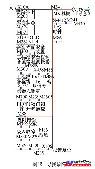
The following is an example: assume that the automation system suddenly stops working during operation. How to find the corresponding problem by monitoring the program and troubleshooting. Figure 18, by monitoring the PLC program, we can see that the output M520 (manipulator pause) in the network 290 has an output. So I went forward and found that only the intermediate relay M88 (adsorption error) is the soft original that turns on the M520. Therefore, it can be seen that the robot adsorption error is the cause of the suspension.
As shown in Figure 19, we then look up M88 and find network 345, which is the program that outputs M88 (adsorption error). It can be known by reasoning that M88 is triggered by the time relay T201 path. Therefore, it can be seen that this accident was caused by the robot R1 adsorption error.
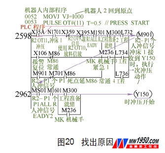
As shown in Fig. 20, the time relay T201 is continuously searched, we can trace back to the network 3430, and it is found that the X31C (the robot 1 suction error monitoring) is the source of the alarm accident. According to the X31C survey, it is known that this is the monitoring signal sent by the robot R1 during the suction process. Therefore, the intermediate relay M371 should also be always in the process of sucking the robot R1, so returning to the network 3493, in order to prevent the M201 from triggering and outputting an alarm, only the normally closed contact of the vacuum sensor of the X309 robot R1 is opened. In order to disconnect the entire line, the PLC will not output an alarm.
Three inferences can be drawn: 1 The robot R1 does not suck the web during the suction process or the downtime caused by the falling of the web during transport. 2 The vacuum sensor of the robot R1 is damaged or is not sensitive to the shutdown. 3 The vacuum pump has no downtime caused by suction. In this way, we can conduct investigations through these three inferences to solve the shutdown accident. The above is the method of troubleshooting the automatic production line by monitoring the PLC program. In this way, maintenance work can be made safer and more efficient.
5 Conclusion
The principle of introducing, digesting and absorbing imported equipment is very useful for future operation, maintenance and improvement. It is necessary to improve the efficiency of the press line, shorten the stamping time, and be able to adjust and optimize when familiar with the principle.