Siemens electric control valve installation steps guide the first step: check
Ultra Plantâ„¢ Grow Light offers One Chip Technology aimed to meet your indoor growing expectation such as improve plants' quality, increase yield, or better the margin, etc., all for helping you realize a higher return on your crops.
From Ultra Plantâ„¢ APP, you are able to schedule the growing process including photoperiod, brightness and spectral in advance. The lighting system will help you grow smarter, easier and better.
1 The valve body shall be installed along the flow direction of the heat medium according to the arrow, and shall not be reversed.
2 The valve must be thoroughly purged before installation to remove welding slag and debris.
3 When the system is warming up, first close the valve front shut-off valve and open the bypass. When the temperature of the secondary heat medium rises to the required temperature, the bypass can be completely closed, the front control valve of the temperature control valve is opened, and the temperature control valve is put into operation. run.
Step 2: Actuator installation:
Pull the valve stem up and attach the actuator to the valve body. Use the inner hexagon or other suitable tool to pre-fix the bottom of the actuator to the valve body connecting ring groove.
Warning: Do not tighten the back rotary actuator manual knob (SAX, SKD series) or manual crank handle (SKB, SKC series) to align the actuator connecting groove with the groove on the top of the stem (Note: SKB, SKC series First remove the lower thread connecting joint of the actuator and put the connecting joint on the valve stem.)
SAX, SKD actuator connection: Use the inner hexagon to tighten the connecting screw until the actuator is tightly connected to the stem.
Note: (1) The screws on both sides should be tightened evenly and should not be twisted. Otherwise, the torque will be generated, which may cause the stem to deform or the actuator bracket to break.
(2) The connecting groove must be aligned, otherwise the stroke will not match or it will fall off during work.
SKB, SKC actuator connection:
Place the attachment snap ring in the groove on the top of the stem. Lift the connecting internal thread joint and catch the snap ring.
Rotate the connecting internal thread joint in a counterclockwise direction and die.
Use the manual knob (SAX, SKD) or the crank handle (SKB, SKC) to lift the stem to the automatic state. At this point, the actuator is automatically aligned, and then the bolts at the valve body connection ring groove are dead. Warning: If it is not corrected, it will be easy to generate stress, which may cause the bracket to break during work!
Warning: (1) Do not hurt the valve stem during the whole installation process. (2) When the SKB and SKC actuators are connected with the valve stem, the internal thread connection must be synchronized with the actuator wire. If it is misaligned, it will cause slippage. Silk, and can not be repaired.
Note: (1) Be sure to restore the manual operation to automatic. Otherwise, the actuator will not operate or cause damage after being energized.
(2) Before the system is subjected to the pressure test, the actuator must be mounted on the valve body. Leave the valve body in the manual open state. After the test is completed, be sure to lift the valve stem to return to the automatic state.
The third step: the outlet water temperature sensor installation:
Immersion temperature sensor (QAE21)
A hole is opened near the outlet of the heat exchanger, the wire holder.
Wire seat requirements: G1/2" pipe thread, inner wire.
The recommended size of the wire seat is matched by the pipe diameter. The length of the wire seat is recommended: see the drawings and tables after the instruction manual.
The bottom of the sensor is threaded around the PTFE tape and fixed to the wire holder in a clockwise direction.
Allow installation location: Locations that are not allowed to be installed:
Note: The seal should be tight to prevent leakage of the outdoor temperature compensation sensor (QAC22):
(1) It is installed in the outdoor shade and is convenient for wiring.
(2) Keep away from doors, windows, etc., and avoid the top of doors and windows.
(3) The height from the ground is ≥2.5m to avoid the touch of idle people.
(4) Punch and nail the wooden tip at the selected position.
(5) Open the front cover of the sensor, fix the sensor with self-tapping, and close the front cover.
The fourth step: controller / electrical control box installation controller installation:
The controller should be installed in a place with sufficient light for easy reading and operation, usually mounted on the DIN rail of the control box.
Electric control box installation:
Select the appropriate location, generally for the wall surface for easy observation operation. According to the installation hole on the back of the electric control box, according to the positioning hole, the expansion bolt will be placed on the electric expansion box, and the nut will be backed up. Warning: The installation of the electric control box must be To stay away from moisture or water leakage, the fifth step: wiring and internal equipment wiring diagram of the wiring controller in the electric control box
Sensor and controller wiring:
QAE21, QAD22 wiring open the QAE21 sensor cover.
Route the signal wires from the side wiring holes.
Connect the B terminal to the controller X1 terminal.
Connect the M terminal to any M end of the controller.
Check if the terminals are loose and the terminals are shorted.
Fasten the cover.
Note: Condensate or moisture should be prevented from entering the junction box along the wiring.
Controller and actuator wiring:
Open the actuator wiring cover.
Open the side knockout hole of the actuator and introduce the wire into the wire box.
The actuator terminal G0 is connected to the controller terminal G0, the terminal G is connected to the controller G, and the terminal Y is connected to the controller output signal Y1.
Restore the cover and confirm that the cover is tightly closed.
Warning: Do not scratch the circuit board when removing the knockout cover and wiring!
It is recommended to install a tight band or take other sealing measures at the drop hole to prevent the condensate from entering the actuator along the wire and burn the circuit board!
DANGER: Do not operate with power, otherwise there is danger of equipment damage or personal injury caused by electric shock!
Warning: Please strictly follow the wiring diagrams attached to the wiring!
note:
(1) It is recommended to select a two-core/three-core shielded signal cable with a diameter of ≥0.75mm2.
(2) The length is m30m. If the distance is longer, it is recommended to shield the signal line from bold.
The shielded signal line should be as far away as possible from the power cable and the motor with signal interference.
The shielded signal cable must not be laid parallel to the power cable.
Note: Prevent shorting at the terminals.
Power supply wiring:
Use a test pencil to check if the power cord is live. It is strictly forbidden to operate!
Connect the power line live/zero line (L/N line) to the L/N terminal of the electric control box.
Connect the transformer output (AC 24V) to the controller terminal G/G0. If the user uses the electric control box provided by our company, the line is connected.
Note: Any installation or damage not caused by this manual will be considered improperly installed by SIEMENS. If it can be repaired, the corresponding cost will be charged.
Http://news.chinawj.com.cn 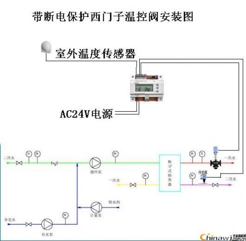 Editor: (Hardware Business Network Information Center) http://news.chinawj.com.cn
Ultra Plantâ„¢ Grow Light is combined our advanced All-In-One technology with patented optical design and customized light full spectrum supported from our experienced LED engineers, plant specialists and other partners working on horticulture.
Ultra Plantâ„¢ is the most versatile horticultural grow lighting fixture for indoor plants with flexible full spectrum, brightness control and uniform, wider light distribution, suitable for top lighting of all types of crops. No matter it applies to anywhere for any crop, Ultra Plantâ„¢ can do perfect work for you.
Uv Grow Light,Uv Light For Plants,Uv Lamp For Plants,Uv Grow Lights For Plants
Feton Corporation , https://www.fetonledlight.com