Zirconia Ceramic Standard Parts The zirconia ceramic oxygen sensor has high mechanical properties and reliability. As a component for purifying exhaust gas, it is used to measure the O2 concentration in the exhaust gas of the vehicle, and then feed the measured value back to the engine feed and fuel supply system. In order to keep the fuel in a fully combusted state. Since all the phases of the ceramic material are completely cubic-type stabilized zirconia, tetragonal and monoclinic mixed partially stabilized zirconia, the mechanical properties are excellent during use, and the heat generated by friction can be reduced. Zirconia Ceramic Standard Parts,Steel Zirconia Ceramic Parts,Anti-Abrasive Technical Ceramic,Alumina Ceramic Molded Parts Dongguan Haikun New Material Co., Ltd. , https://www.hkceram.com
Vericut-based complex surface NC machining NC program verification
**Authors: Paul Henan, Cologne Group Goh, Xinxiang Power Supply Company, He Fang**
The NC program serves as the core information carrier for CNC machining, and its accuracy directly influences the quality of the machined parts. As part of the manufacturing process, the complexity of parts is continuously increasing, which in turn raises the difficulty of CNC programming. This leads to a higher failure rate in NC programs. If the NC code is not properly generated, it can result in over-cutting or under-cutting of the part, as well as collisions between the tool and the workpiece, fixture, or machine table.
**1. Vericut Simulation for NC Program Verification**
In the early stages of production, the NC program was typically verified through actual machine testing or trial cutting. This involved a repetitive process of test cutting, measuring, modifying the program, and re-testing, which was both time-consuming and inefficient. Later, a trajectory display method was introduced, where a computer-controlled plotter simulated the tool path by replacing the tool with a pen and the workpiece with paper. While this allowed for 3D visualization of tool movement and detection of some major errors, it was limited to planar movements and had significant constraints.
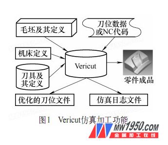
To address these limitations, researchers developed more advanced simulation techniques that could replace trial cutting. This led to the development of computer-based simulation technology for numerical control machining. The workflow of Vericut simulation for NC program verification is illustrated in Figure 1.
**2. Vericut-Based Verification of Complex Surface NC Programs**
To begin with, users must enter the main interface of Vericut and define the working environment. First, set the default units to millimeters by clicking "File → Properties → Default Units = Millimeter." Then, create a new session by selecting "File → New Session" to generate a "*.USR" file. Next, configure the machine structure, select the control system, tool path, blank, and tool, and finally complete the NC program simulation.
**(1) Machine Tool Configuration**
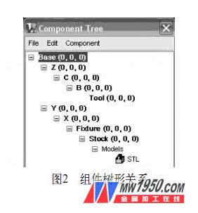
Since CNC machining and simulation are specific to each machine, the components must be configured according to the actual machine. Click “Model → Component Tree†to open the component tree and configure the machine based on the structure shown in Figure 2.
**(2) Selecting the CNC System**
After setting up the machine structure, the next step is to configure the control system. This allows the machine to interpret G-code and perform interpolation calculations. In this case, the FANUC-0 control system is used. To call the control file, go to "Setup → Control → Open" and load the file "C:\cgtech54\library\fan0m.ctl."
**(3) Loading the Blank Model**
Click “Model → ModelDefinition → Model†to load a pre-stored "*.STL" file representing the blank. Similarly, the milling cutter model is imported into the Vericut interface.
**(4) Configuring the Tool**
Define the tool in Vericut by going to "Setup → Tool Manager," creating a new tool library, and adding a φ 8mm ball end mill.
**(5) Loading the NC Program**
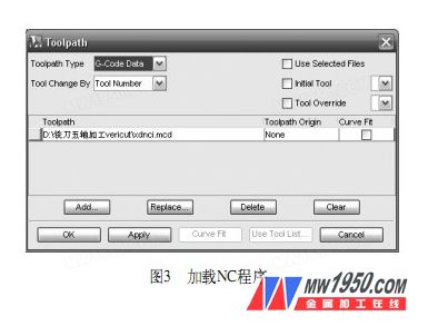
Vericut supports simulation using tool position data from CAD/CAM systems. To load an NC program, click "Setup → Toolpath: Toolpath Type = G-Code Data" and import the NC program generated by MasterCAM, as shown in Figure 3.
**(6) Machining Simulation**
Before simulating, the programming origin must be set, and the blank should be positioned correctly. This ensures the programming origin aligns with the system's coordinate origin. After setup, click the Play icon to simulate the cutting process. The results show that NC programs generated directly by MasterCAM may contain errors due to limitations in the five-axis post-processing function.
By using IMSPost for post-processing, the NC program is refined and re-simulated, resulting in improved accuracy (see Figure 5b).

**(7) Interference and Collision Check**
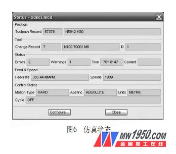
When verifying the NC program in Vericut, the "Info/Status" window provides real-time feedback on tool position, errors, and warnings. A log report is also generated, detailing the nature of the error and the corresponding program segment. The path replay feature allows for immediate correction of problematic segments. If no errors are reported, the NC program is considered verified.
During verification, two errors and one warning were detected. One error occurred at line 8462, where excessive material removal was caused by an inappropriate rapid move. Another error was found in line 8462, which required adjustment. Additionally, a warning was issued for the use of unsupported G-code "G64." After correcting these issues, the simulation confirmed that the NC program was error-free.
In conclusion, Vericut provides a powerful and efficient way to verify complex NC programs, reducing the risk of costly errors during actual machining. It enables engineers to detect and resolve issues before they occur in the shop floor.